Nantucket Vinyl Gate
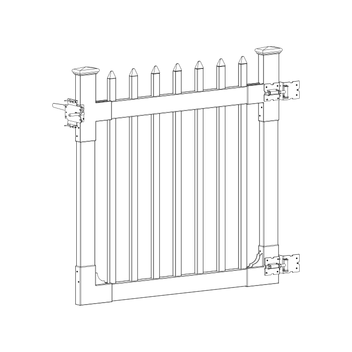
Before You Begin
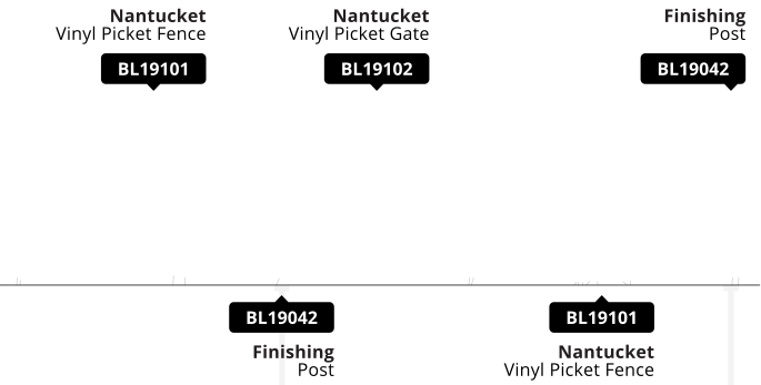
- Call 811 before you dig to check for underground utilities — this gate needs two finishing posts (BL19042) set into the ground.
- See your Nantucket Fence (BL19101) install guide for full panel assembly and layout.
- You should not need excessive force when assembling components.
Returns: Please let us help resolve any issues before initiating a return. If a return is still necessary, it must be initiated with the retailer where the product was purchased.
Need Help or Replacement Parts?
Our US-based customer service team is available Monday-Friday, 9am-5pm EST.
- Website: https://parts.nychbrands.com
- Email: hmmm@wambamfence.com
- Phone: 704-892-5222 or 877-778-5733
For faster service, have your item number (BL19102) and part name ready. A batch lot number (found on the end of the box) is also helpful if available — it helps us identify and resolve any production issues on our end.
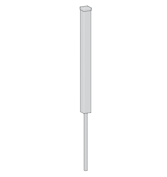
Finishing Post: BL19042
Gates do not come with their own posts
You will need two Finishing Posts — one to finish the fence run, and one to support the gate.
Buying Guide
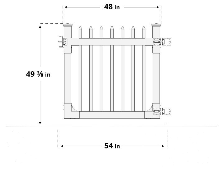
Product Specifications & Dimensions
Post Pounder Considerations
Good
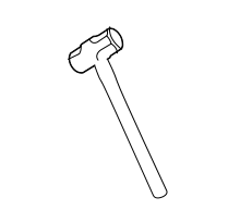
Sledgehammer
10-15lbs.
A basic option for very small projects. Requires two people to keep pipes level during installation.
Better

Manual Post Pounder
12-30lbs.
Best for projects with fewer than 10 pipes. Available at your local hardware store.
Best
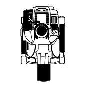
Gas Powered Post Pounder
Rentals are ideal for larger projects. Significantly reduces time and effort required.
Note:
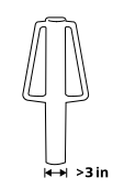
Choose a post pounder with a barrel diameter of 3" or greater. Pounder barrel cannot be longer than 24in.
Required Tools
Drill
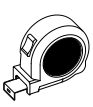
Measuring Tape
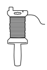
Stringline Reel
Stakes (for stringline)
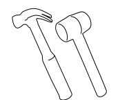
Mallet (Optional for Stakes)
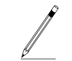
Pencil
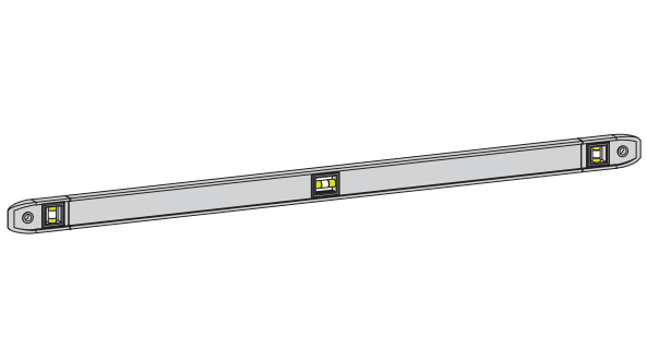
Large Level
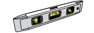
Small Level (for pipe pounding)
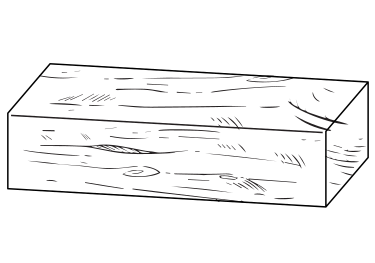
Wood Block
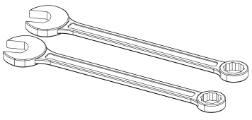
Wrenches
Part Identification
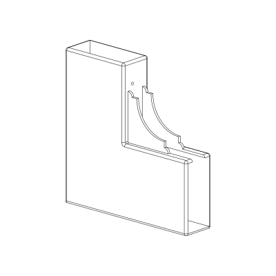
A
Bottom Bracket (2)
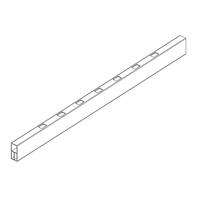
B
Bottom Rail (1)
1½" × 3½" × 47¾"
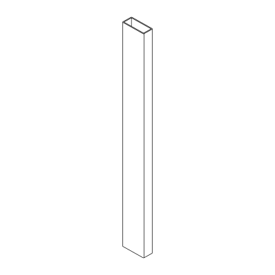
C
Vertical Stiles (2)
1½" × 3½" × 32⅞"
D
T-Bracket (2)
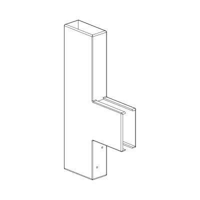
E
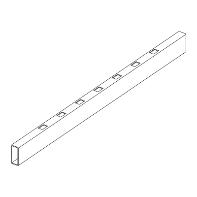
Top Rail (1)
1½" × 3½" × 47¾"
F
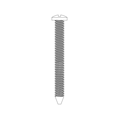
1¼" White Self-Drilling Stainless Steel Screw (20)
G
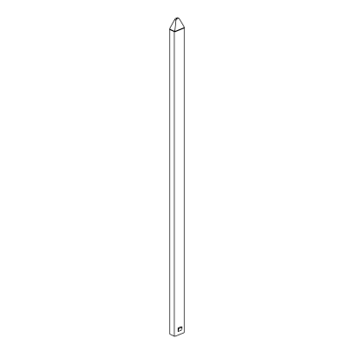
Picket (7)
⅞" × 1½" × 44¼"
H
Post Cap (2)
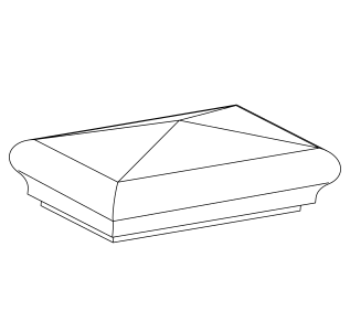
I
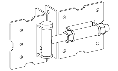
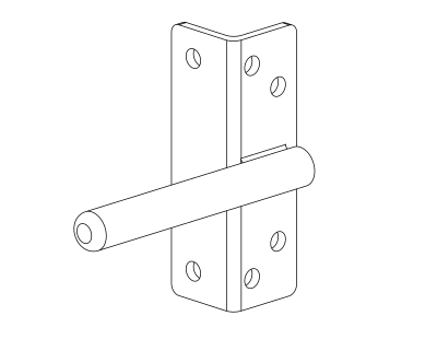
Hinge with Fasteners (2)
with 1¼" Black Stainless Steel Screws (26)
J
4" Tension Pin (2)
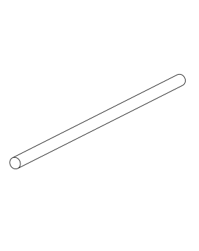
K
Latch Catch (1)
with 1¼" Black Stainless Steel Screws (6)
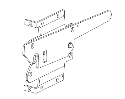
L
Latch Finger (1)
with 1¼" Black Stainless Steel Screws (6)
Hinge Post Support
Your gate will perform best with complete fence panels on both sides. At minimum, the hinge post should be part of a connected fence run — tying it to a panel that continues to another post lets that post help carry the gate's swinging load, instead of the hinge post bearing it alone. If space restrictions make this impossible, contact us for alternative solutions.
Note on Hinges
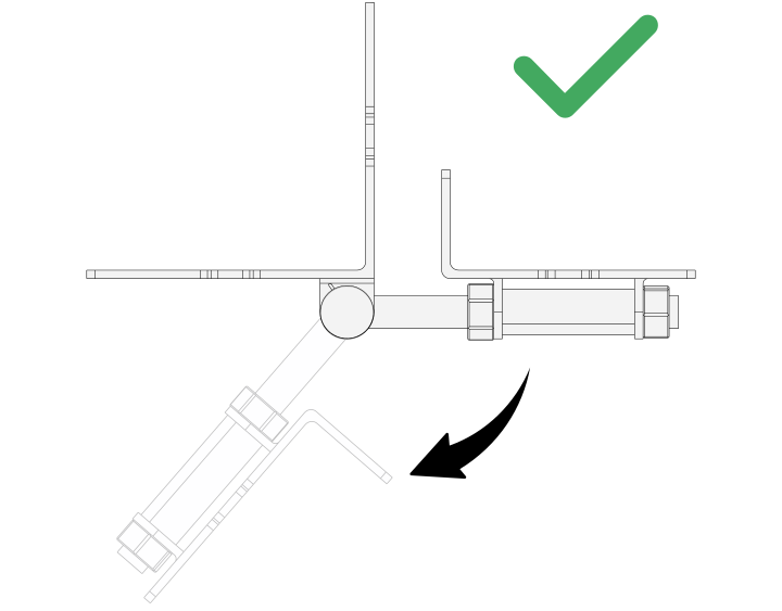
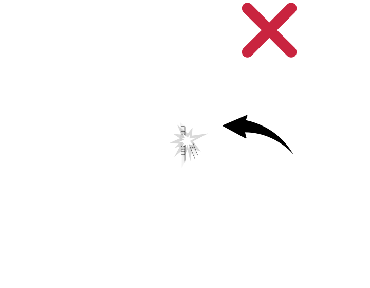
Hinges only open one direction. Decide which way you want your gate to open before mounting your hinges.
Step 1: Bottom Rail Assembly
Parts Required
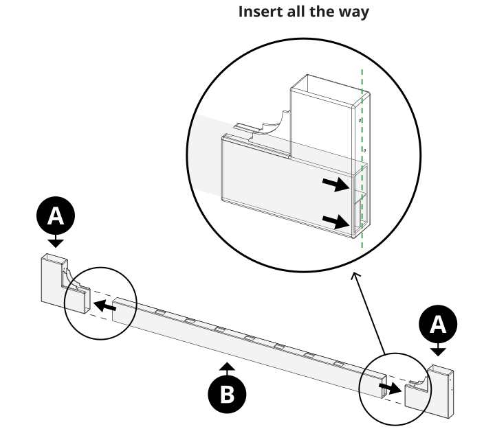
A x2 B x1
Insert the Bottom Rail (B) all the way into both Bottom Brackets (A), until it's seated firmly against the back wall of each bracket. Press firmly. Light force might be required to push the rail to the back of the bracket.
Step 2: Vertical Stiles
Parts Required
C x2
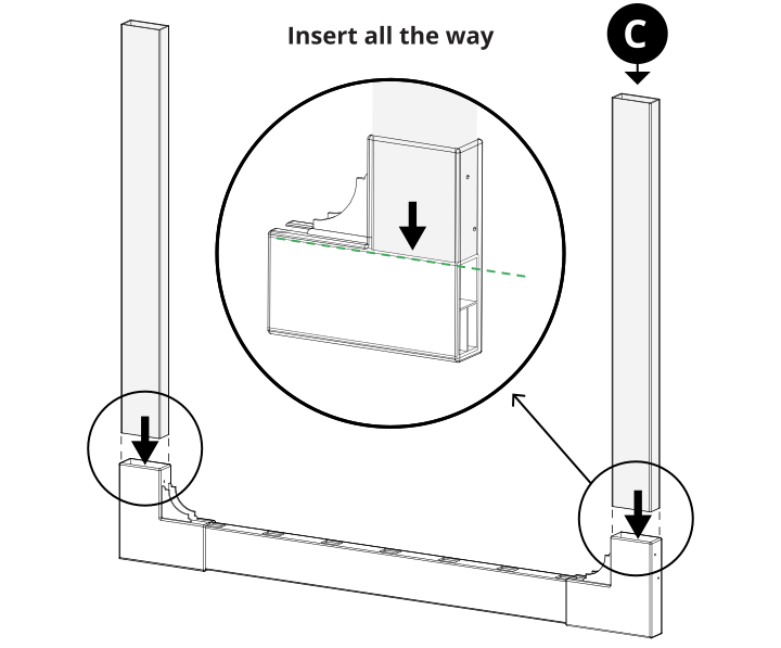
Insert both Vertical Stiles (C) all the way into the Bottom Bracket (A) until they meet the bottom rail.
Step 3: Top Rail Assembly
Parts Required
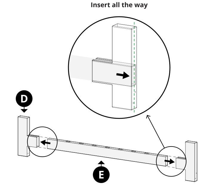
D x2 E x1
Insert the Top Rail (E) all the way into both T-Brackets (D) until it's seated against the back wall of each bracket. Press firmly. Light force might be required to push the rail to the back of the bracket.
Step 4: Frame Assembly
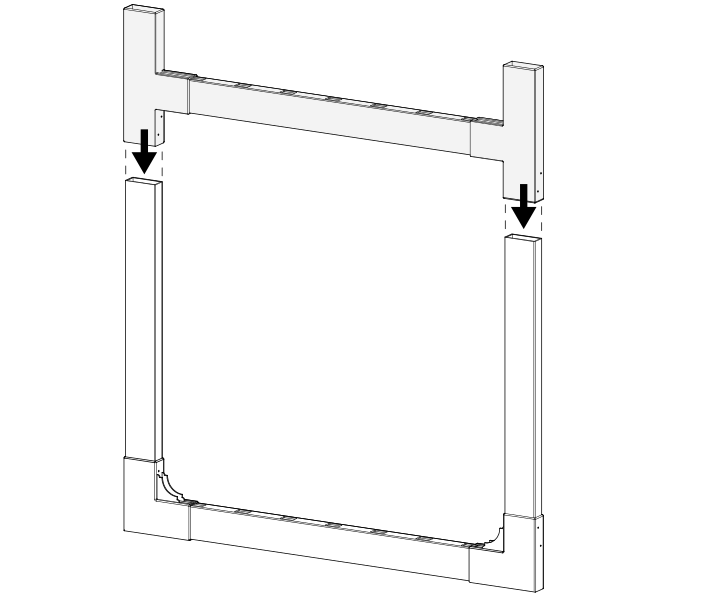
Slide the assembled gate frame top down over the vertical stiles, applying pressure to all four corners to keep a tight fit.
Step 5: Gate Assembly
Parts Required
F x16
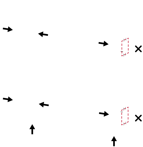
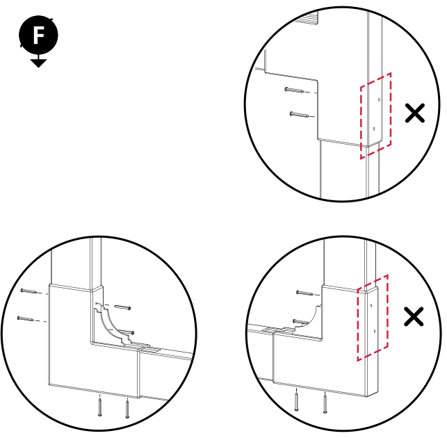
Fasten the gate frame using 16 of the included 1¼" Screws (F). Apply pressure at the corners as you drive the screws to keep the frame square. Do not install screws on the side where your hinges will be located.
Step 6: Insert Pickets
Parts Required
G x7
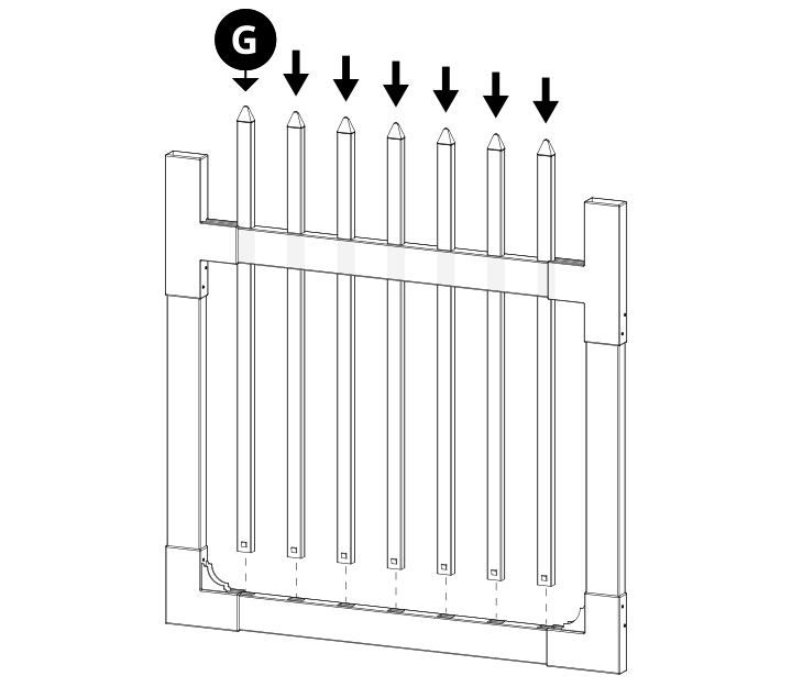
Insert the Pickets (G) through the top rail and down into the bottom rail. Don't be afraid to use muscle — you won't break the vinyl.
Step 7: Post Caps
Parts Required
H x2
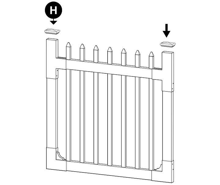
Install the Post Caps (H). Use PVC glue (not included) if you'd like to permanently secure the caps to the T-Brackets.
Step 8: Loosen Hinge
Parts Required
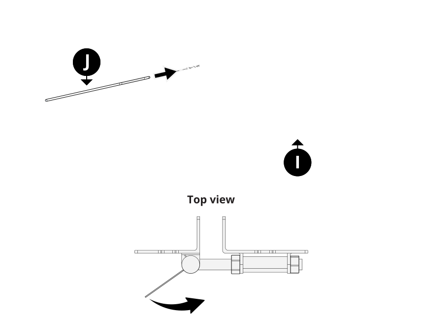
I x1 J x1
Optional, for a slower self-close. Insert the Tension Pin (J) into a hole at the top of the Hinge (I), then rotate it to the right — this takes moderate force. To loosen the tension, turn the pin fully right, remove the smaller pin, let the tension pin ease back to the left, and reinsert the smaller pin into a new hole.
Step 9: Leveling System
Parts Required
I x1
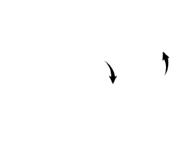
Using two wrenches, loosen or tighten the nuts on the Hinge (I) to adjust the spacing between your gate and the hinge post. This adjustment can also help level your gate later on.
Step 10: Hardware Installation
Parts Required
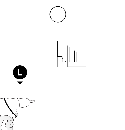
L x1 I x2
Fasten the Latch Finger (L) to the top bracket with 6 of the included 1¼" black self-drilling screws. Fasten the Hinges (I) to the front of the gate brackets with 8 total included screws.
Step 11: Fasten Hinges to Post
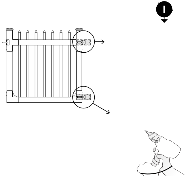
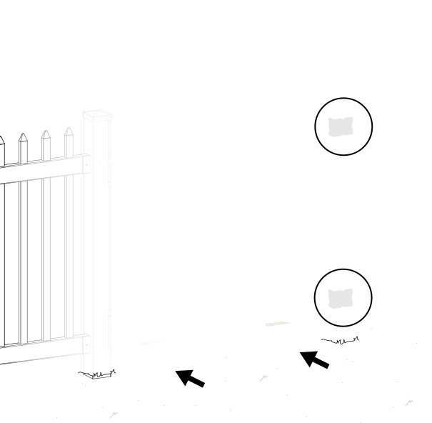
Place wooden blocks under your gate to ensure it is level with your fence rails. Fasten the hinges to the post with 6 total 1¼" black self-drilling stainless steel screws (included with the Hinge and Latch Finger hardware).
Step 12: Secure Gate and Hinges
Open the gate and set it on two wood blocks to keep it level. Fasten the hinges to the post with 4 screws per hinge, then fasten the inside of each Hinge (I) to your gate brackets with 4 total screws.
Step 13: Level Your Gate
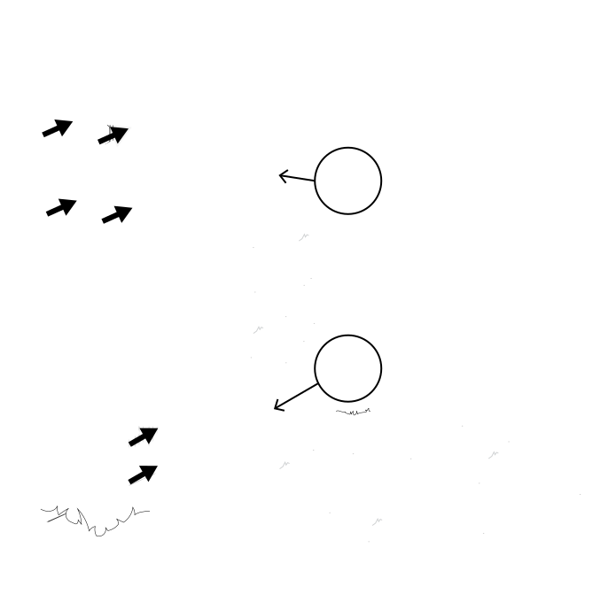
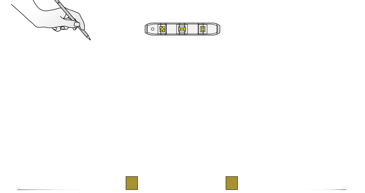
Level the gate to the fence post by adjusting the nuts on the hinges. Check that the gate functions correctly, then mark where you need to install your latch catch.
Step 14: Install Latch Catch
Parts Required
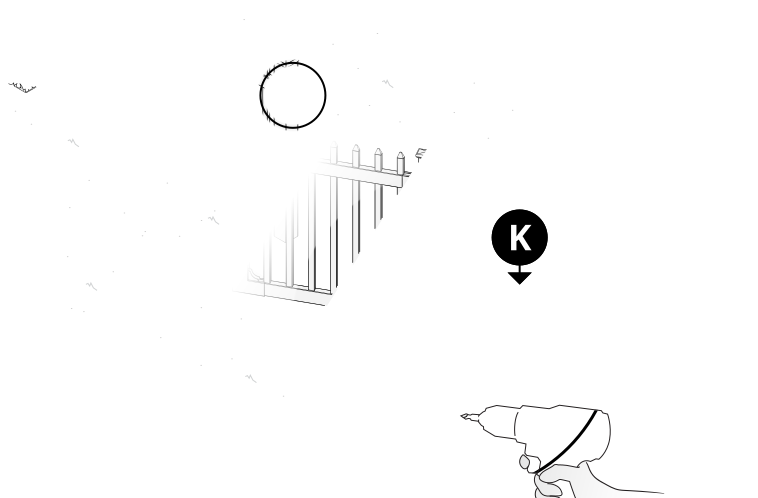
K x1
Open the gate. Align and fasten the Latch Catch (K) with 6 of the included 1¼" black self-drilling stainless steel screws.
Need Help?
- Email: hmmm@wambamfence.com
- Phone: 704-892-5222 or 877-778-5733
- Text: 980-580-6580
